hdmi_text_generator
Kepad-HDMI Interface
Keypad input to generate text on HDMI Display using Zybo
Description
This project aims at building a HDMI and keypad interface using Digilent Zybo Board. Keypad input is given using Pmod Keypad through Pmod port on Zybo. HDMI Output on the board is connected to a 5 inch 800x480 screen.
Keypad has 4 rows and 4 columns having 16 keys representing hex characters from 0 to F. HDMI Display Screen is divided into 20 x 6 display keeping Font Size of 40 x 80 for each character. Initially, screen is blank with white background. On each key press, a character is added to the right of last charcater, Text font color is black.
Reset button resets the screen. Clear button clears the sreen.
Timing Requirements
For 800 x 480 screen,
For Hsync,
Tfp = 40 clock cycles
Tpw = 48 clock cycles
Tdisp = 800 clock cycles
Tbp = 40 clock cycles
=> Ts = Tfp + Tpw + Tdisp + Tbp = 928 clock cycles
For Vsync,
Tfp = (13 x Ts,Hsync) clock cycles = (13 x 928) clock cycles
Tpw = (3 x Ts,Hsync) clock cycles = (3 x 928) clock cycles
Tdisp = (400 x Ts,Hsync) clock cycles = (400 x 928) clock cycles
Tbp = (29 x Ts,Hsync) clock cycles = (29 x 928) clock cycles
=> Ts = Tfp + Tpw + Tdisp + Tbp = (525 * Ts,Hsync) clock cycles = (525 x 928) clock cycles
At refresh rate of 60 Hz, number of clock cycles required is 928 x 525 x 60 = 29232000; So, pixel clock is set to 30 Mhz. Each pixel has 24 bits of data which is encoded into 30 bits of data. This is serialised to 3 different channels. So, serial clock should be able to support 10 times data rate and pixel clock. So, 5 times the pixel clock is chosen as serial clock frequency along with DDR (double data rate).
TMDS Encoding Algorithm
The encoder produces four unique 10-bit characters during blanking and one of 460 unique 10-bit characters during active data. Use of all other 10-bit characters over the link is reserved.
| Parameter | Description |
|---|---|
| D, C0, C1, DE | Input data set. D is eight-bit pixel data, C1 and C0 are the control data for the channel, and DE is data enable |
| cnt | Represents the data steam disparity α - β where α = number of set bits and β = number of unset bits. cnt(t) indicates the disparity after t pixels have been transmitted |
| qout | Encoded output value |
| N_1(x) | Number of set bits in x |
| N_0(x) | Number of unset bits in x |

Serialisation
The stream of TMDS characters produced by the encoder is serialized for transmission on the TMDS data channel. The least significant bit of each character (qout[0]) is the first bit to be transmitted.
Character Display
Font ROM: The appearance of the characters on the screen is determined by a “font ROM”. The font ROM contains the pattern of pixels that should be displayed on the screen when a particular character needs to be displayed. The bits within the font ROM indicate which pixels of a 8 x 16 bit tile should be displayed in the ‘foreground’ and which pixels on the display should be displayed in the background. A ‘1’ in the font ROM indicates the corresponding pixel should be displayed in the foreground (i.e., white
in our case) while a ‘0’ in the font ROM indicates that the corresponding pixel should be blanked or put in the background (black in our case). The text below demonstrates the contents of the font ROM for the upper-case character ‘A’:
"00000000", -- 0
"00000000", -- 1
"00010000", -- 2    *
"00111000", -- 3   ***
"01101100", -- 4  ** **
"11000110", -- 5 **   **
"11000110", -- 6 **   **
"11111110", -- 7 *******
"11000110", -- 8 **   **
"11000110", -- 9 **   **
"11000110", -- a **   **
"11000110", -- b **   **
"00000000", -- c
"00000000", -- d
"00000000", -- e
"00000000", -- f
Character Memory: In addition to the font ROM, we use a “character memory” that stores the character value at each of the 20x6 character locations on the display. The minimum size of this memory is 20x6x4 bits to provide enough room to store characters (one nibble each) for each of the 20 columns and 6 rows.
This memory has two memory ports: a character read port and a character write port. The read port is needed by the character generator to read the character value of the current character location. The write port is used to update the contest of the character display.
The char_read_addr port is a 7 bit signal used to determine which location in the character memory to read. The result of the read is available on the char_read_value. Like the font ROM, this character ROM will provide the character result one clock cycle after the address is provided.
The second memory port is the character write port. This write port is used to update the contents of the character memory so the display can be changed. This port operates simultaneously with the read port so the character display can access characters while the character memory is being updated. Three signals are used for this port. The char_write_addr signal is used to indicate the address within the character memory that will be updated. The char_write_value is the value that will be written at this address. The char_we signal is the control signal to enable a write into the character memory. When the char_we signal is asserted, the value on the char_write_value signal will be written at address char_write_addr at the next clock edge.
Character Memory is used to give video_data to TMDS signal generator.
State Diagram for Keyboard Input
After each 4 ms, a column is made low. Then, each row is checked for low signal. Corresponding after each 16 ms, it is recorded whether a key was pressed. Then, cur state is recorded. If last state was not key pressed and cur state is key pressed, then keypad writes to character memory.
Timing Analysis
System Clock System Clock (Time Period) = 8 ns;
Worst Negative Slack (Pulse width) = 2 ns
Pixel Clock Pixel Clock (Time Period= 33.33 ns
Worst Negative Slack (Setup) = 5.44 ns
Worst Negative Slack (Hold) = 0.177 ns
Worst Negative Slack (Pulse width) = 16.167 ns
Serial Clock Serial Clock (Time Period) = 6.66 ns;
Worst Negative Slack (Pulse width) = 4.511 ns
Resource Utilisation
LUTs = 1189 FFs = 690
Results on Board (HDMI Display)
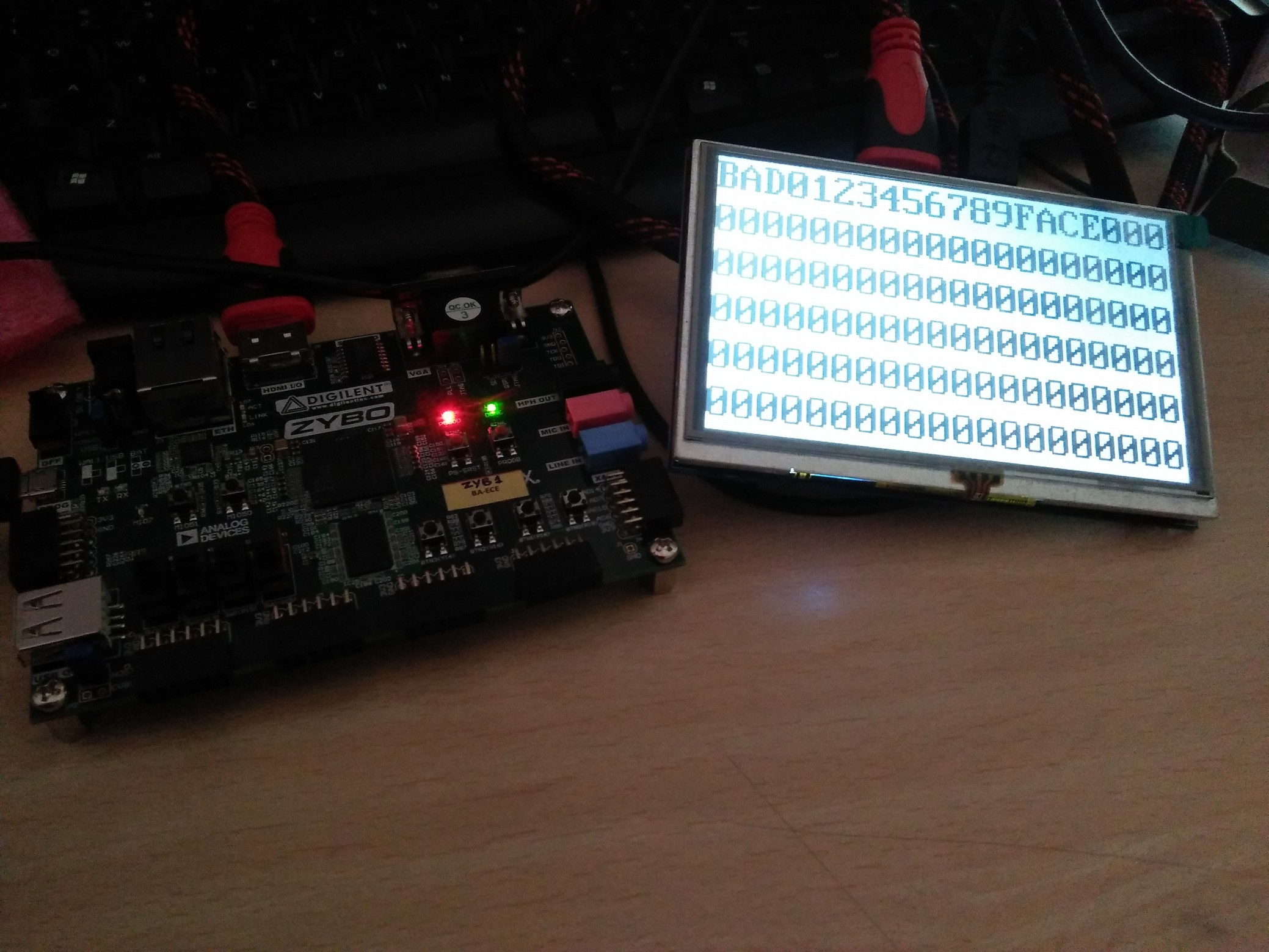
Conclusion
20 x 6 Text Displaying hex characters was implemented using Zybo board HDMI Output printing characters on screen taking input from Pmod Keypad.
References
Digital Visual Interface Specification
VGA Text Generator- https://ece320web.groups.et.byu.net/labs/VGATextGeneration/VGA_Terminal.html